

Customer Solut Enerji, solar EPC company
Location Alaçatı (Çeşme, İzmir), Türkiye
Building Twin villa with a multi-plane roof
Task Initial roof assessment and module layout preparation
Used Render-a: a measurable 3D roof model built from drone imagery
Result Initial roof assessment and layout preparation about 15% faster (as reported by Solut Enerji) |
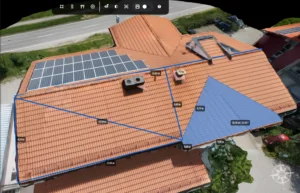
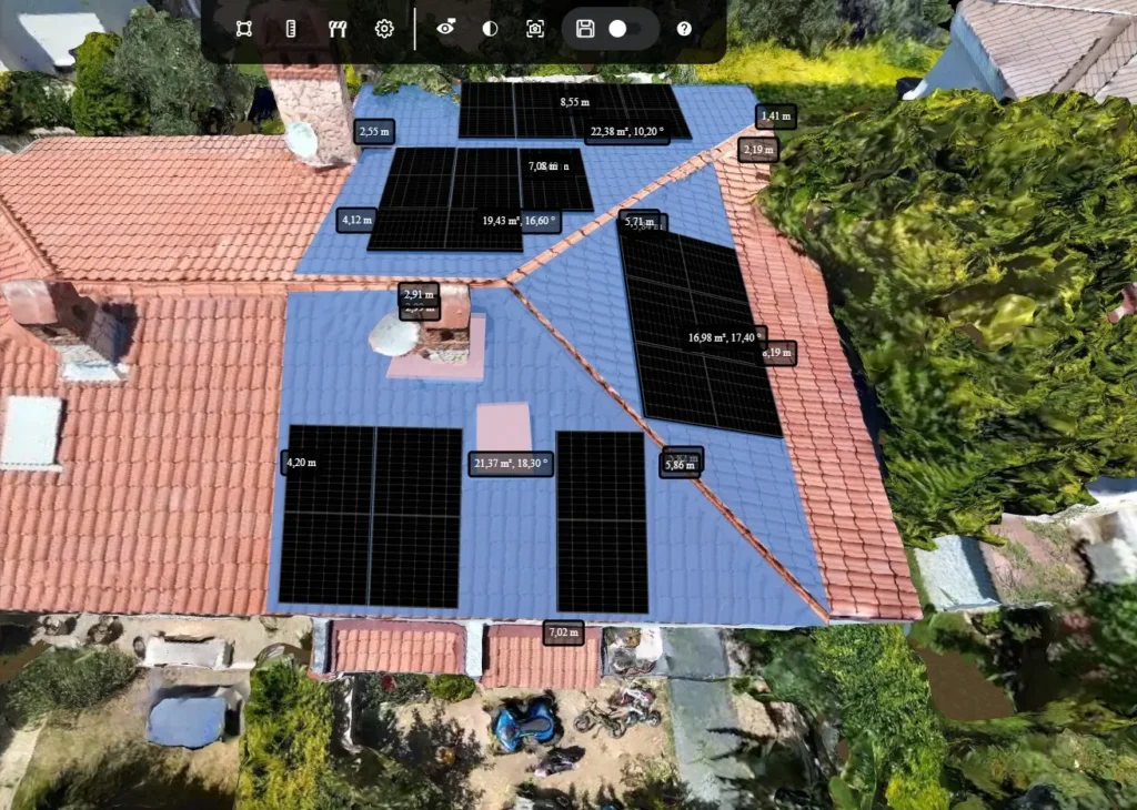
This case study shows how the solar EPC company Solut Enerji prepared a twin villa in Alaçatı for a PV system. The roof is made up of many small planes, each with its own pitch and orientation. On top of that there is a chimney, other rooftop structures and dense trees around the property.
Instead of piecing the roof together plane by plane from photos and notes, the team assessed it on a measurable 3D model in Render-a. According to Solut Enerji, this made the initial roof assessment and module layout preparation about 15% faster.
The challenge: one roof, many planes
On paper, a villa is not a big project. In planning, it can still take more work than a large warehouse roof. This building had no continuous surface where a row of modules could simply run from end to end.
Many small planes, each with its own pitch and orientation
The roof consists of several small planes that face different directions and sit at different pitches. For solar design, that means every plane has to be assessed on its own. A plane that looks large in an aerial photo may hardly be usable because of its orientation or a structure on it.
Chimney, rooftop structures and roof edges
A chimney and other rooftop structures cut into the areas where modules could go. The transitions between planes and the roof edges also dictate setbacks. The roof area is therefore not the same as the usable area.
Dense trees around the building
The villa is surrounded by trees. They are part of the project context: which planes border the trees, and how easy is it to access the roof? These questions are easier to answer when the roof and its surroundings are visible in the same model.
Two halves of one building, clearly separated
In a twin villa, the roof planes belong to two separate homes. Good planning needs a clear answer to which plane belongs to which half, and how much usable area is left on each side.
The homeowner wants to understand the layout
A table of measurements does not convince a homeowner. Solut Enerji wanted to show where the modules would go before installation, in a way anyone could understand without technical knowledge.
The workflow: from aerial images to a solar panel layout on a 3D roof model
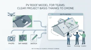
The Solut Enerji team set up the project in Render-a using drone imagery of the building. Photogrammetry turns the overlapping images into a to-scale 3D roof model that can be measured. That model is the core of any [3D drone roof measurement](https://render-a.com/drone-roof-survey/).
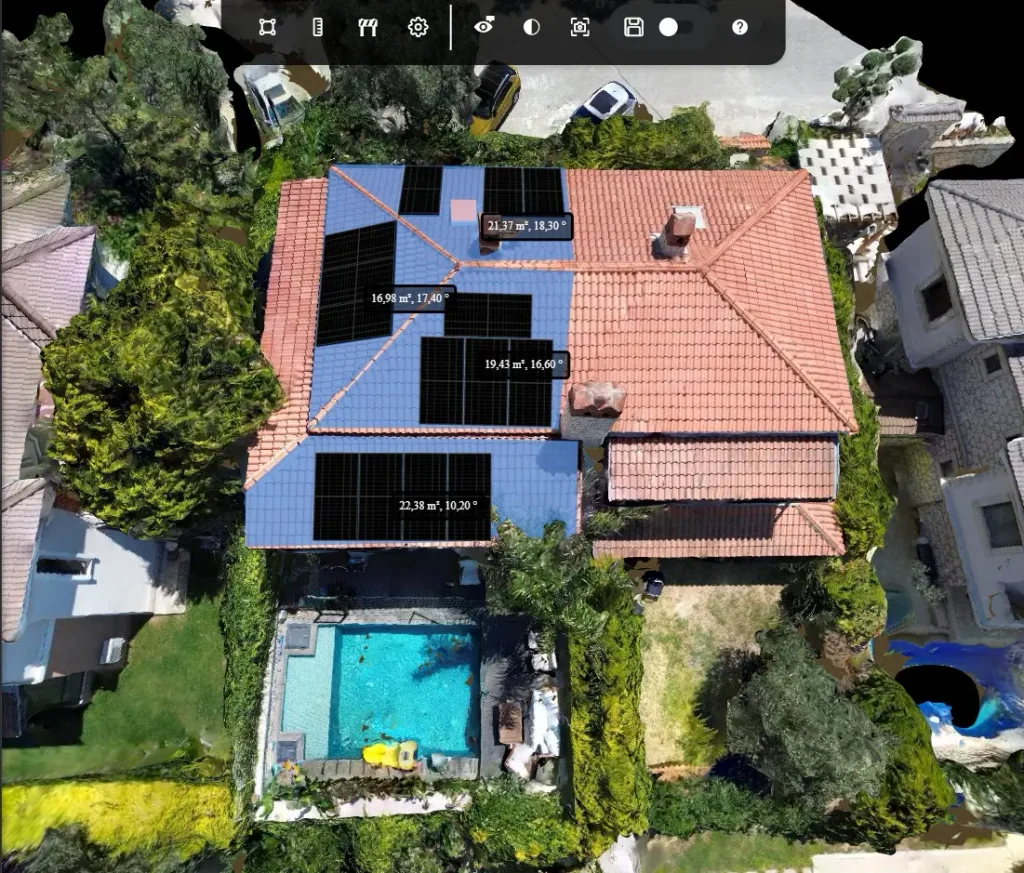
The workflow in five steps:
1. See the roof as a whole. The team rotates the model and sees the full roof together with its surroundings.
2. Assess each plane on its own. Pitch, orientation (azimuth) and area are read directly from the model for every plane, not estimated.
3. Account for obstructions. The chimney, rooftop structures and edge zones are identified before they get in the way of the layout.
4. Select usable planes and place modules. The module layout is built on the suitable planes.
5. Share the result with the customer. The layout on the 3D model is shown to the homeowner as a clear visual.
Because the measurements and the layout live on the same model, nothing has to be re-entered into a second tool. From that basis, Render-a can also produce the module layout and a priced solar proposal from the same model. Teams that continue the design in their own planning software can reuse the roof model in PV*SOL
The result: about 15% faster to the first layout
According to Solut Enerji, the team completed the initial roof assessment and module layout preparation about 15% faster with Render-a.
– About 15% faster initial roof assessment and layout preparation
– Multi-plane roof geometry assessed on a 3D model, one plane at a time
– Chimney, roof edges and usable areas clearly visible before planning
– Module layout as a visual for the customer, easy to understand without technical knowledge
What the 15% measures, and what it doesn’t
We want to put the number in context. The 15% refers to one clearly defined step: the initial assessment of the roof and the preparation of the module layout. It says nothing about the overall project duration, later energy yield or installation. A shading simulation is not part of this case study.
## What solar installers can take from this project
Multi-plane roofs are not unique to Alaçatı. Dormers, hips and valleys, additions and mature trees are common on single-family and semi-detached homes in the US and the UK. In our view, this project shows three points that apply everywhere:
1. Planes first, modules second. On a multi-plane roof, placing modules first means planning on planes that later turn out to be unsuitable. Assessing every plane belongs at the start.
2. Obstructions belong in the first assessment. A chimney that only shows up during installation costs time and trust. [Roof measurements on a 3D model](https://render-a.com/drone-roof-survey/) show it at the planning stage.
3. Customers decide with visuals. A layout on a 3D model tells a homeowner more than a list of square meters and angles.
Planning roofs with many planes yourself? Try the workflow on your own project.