

Render-a Technical Documentation
Overview of the Render-a workflow, drone capture, cloud photogrammetry, 1:1 scale digital twins, measurement, solar design, export, and reporting.
A technical guide covering Render-a’s drone-based data capture, cloud photogrammetry, 1:1 scale 3D digital twin, measurement, solar design, export, and reporting workflows in a single reference.
Render-a Technical Documentation
About This Document
This text has been organized based on the product terminology and usage flow in the supplied technical document. No certainty is claimed for technical details that are not explicitly documented within the product.
Important: This guide uses original illustrations that explain the function, rather than actual application screenshots. If interface labels change, read the text as describing the functional flow rather than exact UI wording.
1) Getting Started and Core Concepts
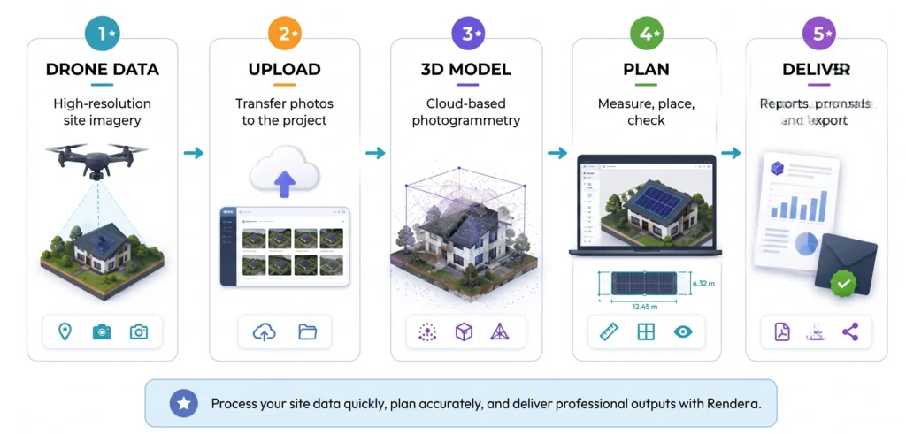
Render-a is a platform designed to turn drone imagery into 1:1 scale 3D digital twins through a cloud-based photogrammetry workflow. Within Render-a Solar, site survey, measurement, panel layout, energy yield estimation, reporting, and proposal preparation can all be carried out within the same project flow.
Alongside solar, the platform provides a reality-capture infrastructure that can also be used for roof, façade, scaffolding, terrain/topography, and general 3D modeling scenarios.
Use Cases
- Roof / PV systems — roof geometry, pitch, area, obstructions and panel layout; output: 1:1 3D model, measurements, solar design.
- Terrain / Ground-mount — modeling the site’s topography and obstructions; output: 3D terrain model, measurement and design input.
- Façade — measuring vertical surfaces and modeling details; output: façade measurements, 3D surface.
- Scaffolding — pre-assessing façade and ground geometry; provides data for material/layout planning.
- General object / Product — bringing objects from photographs into a 3D environment; 3D model and exportable data.
Core Terminology
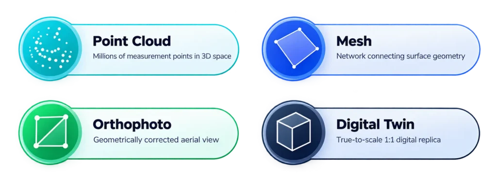
- Digital Twin — the scaled digital counterpart of a real scene or object.
- Point Cloud — a data structure formed by a large number of points in 3D space. Point density is a key input to the geometric detail achieved.
- Mesh — a surface network of triangles/polygons derived from point data.
- Orthophoto — a measurement-ready top-down image produced by correcting perspective and geometric distortion.
- Overlap — the proportion of the same surface area seen in common by consecutive images.
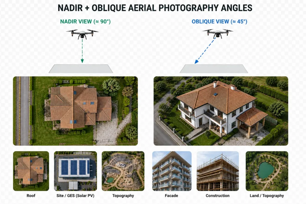
- Nadir — a shooting direction where the camera looks approximately straight down at the surface.
- Oblique — a shooting direction where the camera looks at the surface at an angle, particularly used for vertical surfaces.
- DIN — used in this document to refer to an accuracy and quality approach in engineering measurement. Render-a’s official product communications emphasize 1:1 measurement and DIN-standard precision; a specific DIN 18710 accuracy class or a ±cm value is not assumed in this guide.
Creating an Account
- Sign up at app.render-a.com.
- Enter your company/individual account details.
- Complete email verification.
- After logging in, review the demo project or create a new project.
System and Browser Requirements
- An up-to-date version of Chrome, Edge, or Firefox.
- WebGL 2.0 support for the 3D Viewer.
- A desktop/laptop computer is preferred for large models.
- A high-speed internet connection is recommended for large data sets.
2) Drone Flight Guide and Data Capture
Drone and Sensor Selection
Render-a is designed to work with imagery from different drone sources. Preserving GPS/RTK metadata is important for scale and positional accuracy. RTK-enabled systems provide a stronger starting data set in terms of positioning.
Rule of thumb: Capture quality matters as much as the drone model: sharp images, consistent exposure, sufficient overlap, and the right angle combination directly affect the model outcome.
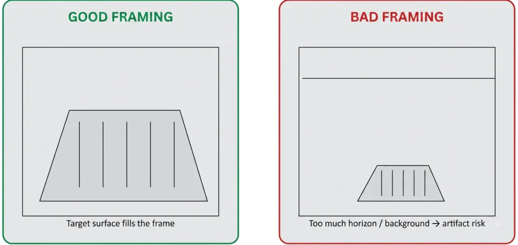
The target surface should fill as much of the image as possible. As unnecessary sky, horizon, and background increase, so does the risk of the system producing off-target geometry.
- Place the target object in the center and majority of the frame.
- Avoid wide horizon/background gaps.
- Keep lighting conditions consistent within the same data set.
- Cover the entire target surface from different angles with sufficient overlap.
Overlap Requirement
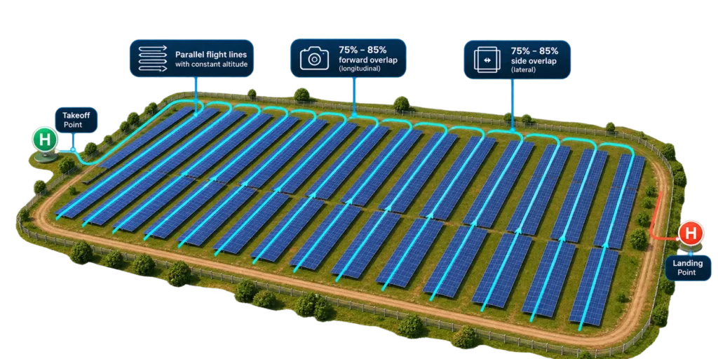
2.3 Ground-mount – Grid Flight for Ground-Mounted Solar Power Plants
To obtain a highly accurate 3D model in large areas, a grid flight is performed in parallel strips. The goal is to image the entire area completely and homogeneously with high and consistent overlap.
Image Annotations (on the field):
- Take-off Point
- Parallel strips, constant altitude
- 75% – 85% front overlap (longitudinal overlap)
- 75% – 85% side overlap (lateral overlap)
- Landing Point
Flight Parameters
- Altitude: Determine based on field width and GSD requirement. Lower altitude = higher detail.
- Camera Angle: Nadir (90° straight down) shooting is recommended.
- Overlap Rates: Front overlap ≥ 75% • Side overlap ≥ 75%
- Flight Speed: Fly at a constant and stable speed.
- Lighting Conditions: Cloudy or sunrise/sunset hours are ideal. Avoid sharp shadows.
- Wind: Flight stability and overlap quality decrease in strong winds.
- Battery Planning: Use sufficient batteries and backup batteries according to the area size. Leave a safe margin for landing.
What is Overlap?
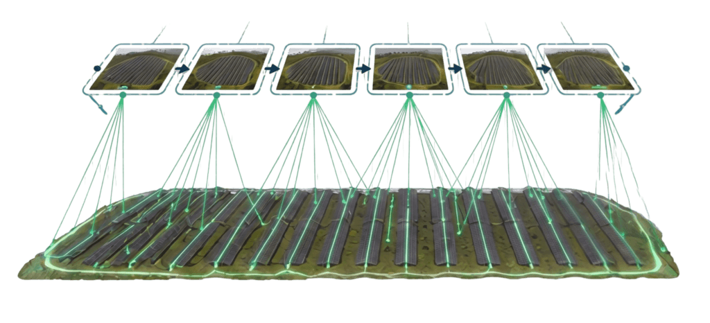
Overlap is the common area ratio between consecutive photos. High overlap allows the software to better match common points and increases accuracy.
- New Photo
- Overlapping Area
- Front Overlap (Longitudinal) ≥ 75%
- Side Overlap (Lateral) ≥ 75%
Why is it So Important?
- Ensures complete area coverage.
- Prevents the formation of gaps in the 3D model.
- Increases accuracy and detail quality.
- Reduces the need for repeated flights.
Flight Planning Steps
Flight Planning Steps
1. Define the Area
Determine the boundaries of the area you will fly over.
2. Determine Grid Direction
Choose the strip direction to be perpendicular to the wind direction.
3. Set Parameters
Set the altitude, overlap, speed, and camera angle.
4. Check Battery and Backups
Make a battery plan that will cover the entire area.
5. Start the Flight
Execute the plan, monitor the flight, and intervene when necessary.
6. Check the Data
Check the number of photos and coverage after the flight.
Pro Tip
In cases where the area is very large, plan the flight in multiple sorties (battery changes) and leave an additional 10-15% overlap margin between the strips. Saving flight logs and weather conditions provides a great advantage in potential repeat flight plans.
Recommended grid flight pattern for ground-mount PV
- Maintain as constant an altitude as possible across the site.
- Target at least 75% side overlap on parallel strips.
- Make extra passes over site edges and corners.
- Automatic grid/waypoint planning can be used on large sites.
Narrow Streets and Façades
- Maintain a safe and controlled distance from the façade.
- Proceed in regular strips from top to bottom or bottom to top.
- Leave sufficient overlap between strips.
- Prioritize flight safety and position control in areas where GPS signal may weaken.
- Check required flight permits in advance due to pedestrian/vehicle traffic and local regulations.
Camera Settings and Shooting Angle
- Use the lowest possible ISO together with a shutter speed that prevents motion blur.
- Keep exposure as consistent as possible throughout the data set.
- Use nadir shots for roofs/topography; use oblique shots for façades and vertical details.
- Using both angle types together strengthens surface coverage on complex projects.
Data Capture with Hyperlapse Video
Render-a’s current product communications state that Hyperlapse videos can be used in the 3D modeling workflow. Since details of the video-based workflow, such as video codec/fps and minimum duration, depend on the product version, current in-app requirements should be used as the basis when setting a field standard.
Weather Conditions and Shadowing
- Prefer hours with fewer hard shadows, or diffuse light.
- Strong wind can negatively affect drone stability and image sharpness.
- Follow the drone manufacturer’s limits in rain/humidity conditions.
- Minimize sudden changes in lighting conditions during the shoot as much as possible.
Common Data Capture Mistakes
- Working with images that have passed through compression apps like WhatsApp; metadata loss can occur.
- Mixing images shot on different days or under very different lighting conditions into a single data set.
- Flying quickly with low overlap.
- Using so much background that the target object is left too small.