

Render-a Guide: Data Upload, Cloud Render Process, and 3D Measurement
How to upload drone imagery, run and track a cloud render, validate coverage with Preview, and measure distance, area, and pitch on the 3D model.
Creating a New Project
- Log in to your Render-a account.
- Start the new project creation flow.
- Enter customer/project information.
- Select photos or a supported data source.
- Once the upload is complete, start the render process.
Supported Data Sources and Limits
Render-a’s public product information states that data transfer is supported via Google Drive, Dropbox, and OneDrive. Chunked upload is recommended for very large files. The public FAQ does not state a strict technical file-size limit.
| Source | Use |
| Local files | Uploading the photo set directly to the project |
| Google Drive | Transfer from a cloud data set |
| Dropbox | Transfer from a cloud data set |
| OneDrive | Transfer from a cloud data set |
| Hyperlapse video | Video-based 3D modeling workflow |
Render Process and Status Tracking
Once a render is started, you can track the process status in the project details. Processing time depends on the number of photos, resolution, data size, and the geometric complexity of the project. Typical roof projects can complete in roughly half an hour, while large terrain projects can take longer.
Chunking Large Projects
- Split the upload into chunks for very large data sets.
- Reduce unnecessary or repetitive frames in the initial upload.
- Upload additional data after the project is created if needed.
- The goal is not data loss, but breaking the transfer and processing load into manageable pieces.
Validating the Data Set with Preview
- Generate a Preview.
- Check the model’s overall volume with Bounding Box.
- Find low-overlap areas with Show Gaps.
- Use Hide Backfaces to check surface orientation when unclear.
Checkpoint: Preview is the fastest quality-control step for assessing data set quality before a full render.
3D Digital Twin and Measurement Tools
3D Viewer Workspace
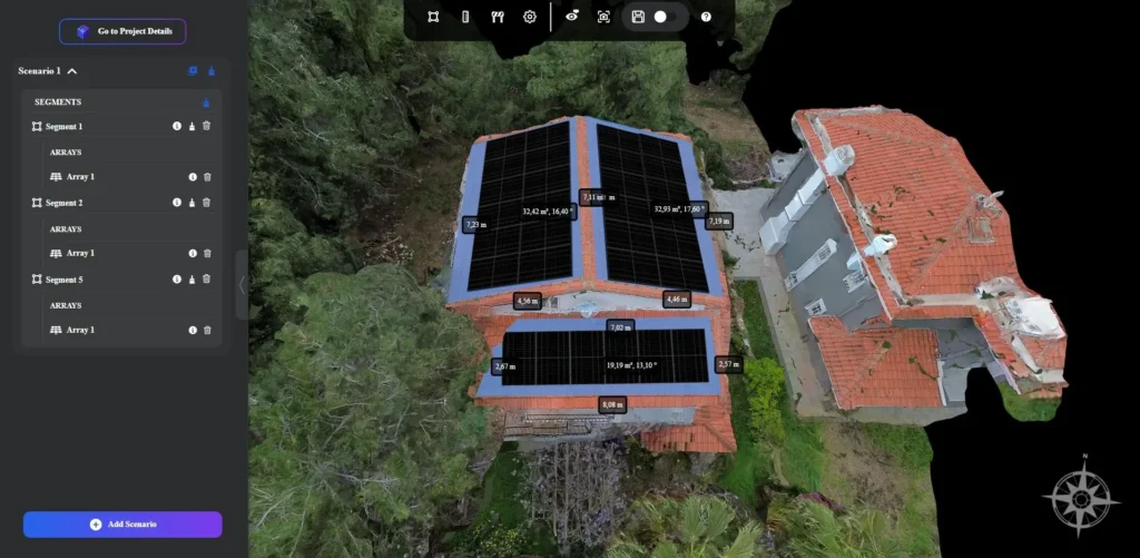
Within the 3D Viewer you can navigate the model and perform measurement and solar design operations. Before panel layout, a suitable area is defined; the panel brand/model is then selected and panels are placed one by one or with the fill tool.
Measurement Tools
| Tool | What it measures | Use |
| Length | Distance between two points | Roof edge, span, site distance |
| Height | Vertical difference | Façade, parapet, obstruction height |
| Area | Polygon surface area | Roof/site area |
| Pitch | Surface angle relative to horizontal | Roof pitch and topography |
1:1 Scale and the DIN Approach
Render-a’s product communications emphasize 1:1 scale digital twins and DIN-standard precision. That said, this document does not define a specific DIN 18710 accuracy class or a single ±cm tolerance guaranteed across all projects.
Measurement quality: 1:1 output is not independent of field data-capture quality. GPS/RTK quality, image sharpness, overlap, camera geometry, and data set integrity all affect the measurement result.
Panel Layout
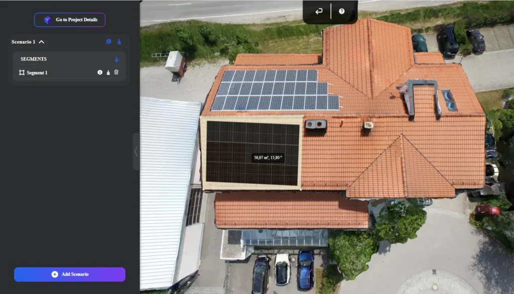
- Define the usable area first.
- Select the panel brand/model from the panel configuration section.
- Place panels one by one or with the fill tool.
- Adjust rotation with the right mouse button if needed.
- Check obstructions, edges, and maintenance clearances as part of the design.
Camera Controls
- Right-click and drag to rotate the camera.
- Left-click and drag to pan the model.
- Double-click a point to center on it.